NOTICE: This tutorial is out-of-date! The updated tutorial can be found at http://www.tktalkie.com/tutorial
.
This tutorial is for Version 1 of this project. There is now a Version 2 available. In order to build Version 2, follow the tutorial below, and the alternate steps for Version 2 are marked below.
It’s been a lifelong dream of mine (as well as many, many others out there) to own my own set of Stormtrooper armor. I, like may others, was finally able to do this when Anovos offered up their kits last year and made them super affordable. Cue dream montage in 3…2…
 I’ve had a blast building my kit and helping and being helped in the process by so many great people that are so ready to offer up their knowledge via the Anovos Facebook group and of course WhiteArmor.net.
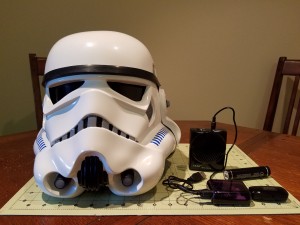
So here’s my attempt at giving back. I purchased a wireless mic system from Wireless Trooping Systems and an Aker 10 watt speaker off eBay, but wanted to add the really cool voice effects. You can buy effects boxes, and they are all great, but I, like so many, am on a budget (putting 2 kids through college with a 3rd on the way is NOT cheap lol…)
I love to tinker with Arduinos and such, and stumbled across a video for the Teensy 3.2 and the Teensy Audio Shield and was blown away by what it could do. And it’s inexpensive. I started thinking…”what if…”
Fast-forward about a week later and I have a pretty decent working voice-effects box for around 50.00 (not including the speaker or the wireless microphone system…which is awesome btw..) It was not very difficult. I built on the plethora of examples and tutorials that come the Teensy software. And to date, it has the following features:
- Is voice-activated (no Push-To-Talk…but it could be added pretty easily)
- Is fully customizable – From the startup sound to the effects, you can use pretty much whatever you want (though honestly, there are only a few TK voice effects to realistically use)
- Did I mention it is FULLY customizable? Since you have the source code you can do pretty much whatever you want with it!
You can get the source code and instructions from my Github repository.
Ok, enough chatter (see what I did there?) Let’s get to it!
Stuff You’ll Need
I built my effects box using a Teensy 3.2 and Teensy Audio Shield, although you can actually use other boards if you want. Teensy is pretty powerful and just makes it easy!
If you are building Version 2, you’ll need to get the pre-pinned Teensy, or else solder your pin headers the same as the pre-pinned Teensy. YOU WILL NOT NEED THE SOCKET SET OR THE HEADER PIN SET LISTED BELOW.
The following are optional, but I recommend grabbing them:
Tools You’ll Need
- Soldering iron and solder
- Magnifying headset if you’re over 40 like me and can’t see anything within a foot of your face 😉
- Wire
- Wire strippers
The following are for making an optional case:
- X-acto knife (for fine trimming)
- Drill and various size drill bits
- Some type of work mat (if you are working on your kitchen table like me)
- Needle (or small) files
Getting Started
NOTICE: The link to the Arduino software below is the general downloads page…the current version of the TeensyDuino software DOES NOT work with the latest version of Arduino (1.6.9 as of this writing) so you’ll need to grab an older version.
Once you have your Teensy and Audio Shield in hand, you’ll need to install the Arduino software as well as the Teensy software, called TeensyDuino. Take some time and familiarize yourself with the examples and tutorials under File > Examples > Audio and File > Examples > Audio > Tutorial. There is a lot of great stuff there. Additionally, watch the Teensy Audio Tutorial and Workshop video on Youtube to get an idea of what you can do with this awesome piece of tech!
If you are impatient, then just keep reading 🙂
Install the Software
Once you have downloaded the Arduino and TeensyDuino software, install the Arduino software FIRST. Then, install the TeensyDuino software (you’ll need to tell it where the Arduino software is located.)
Soldering and Connecting the Boards
If you are building Version 2 using the pre-pinned Teensy (or soldering the pins on the same way as the pre-pinned version), skip the steps regarding the header pins and sockets and just solder the Teensy directly to the Audio Shield according to the directions in the Version 2 tutorial, being careful to align the pins correctly. (See Version 2 for reference.)
I actually soldered mine backwards, with the sockets on the Teensy and the header pins on the Audio Shield
If you did not get the pre-pinned Teensy, then you’ll need to solder the header pins on the Teensy. Then solder the sockets on the Audio Shield. Put the short end of the header pins on the “top” of the Teensy…that is, the side that has the micro USB connector and the programming button. The long part of the pins should point up and away from the side with the usb connector and button. On the Audio Shield, solder the short end of the socket pins to the underside…or the side that has the SD card reader and headphones jack. The long end of the sockets should be on the opposite side. It’s important to get these right so that the connections are correct when you put these together!
Once you have everything soldered up, connect the shield to the Teensy, being careful that the pins are lined up correctly. Check the 4 corner pins on each board and make sure they will line up with you connect the boards together. They are (clockwise, holding the Audio Shield looking at the side opposite the SD Card reader and headphone jack)
If everything is lined up, the micro USB of the Teensy and the headphone jack of the Audio Shield should be facing the same direction.
Sound Files
You can make your own WAV files, or you can download a zip file with WAV files to get started. Be sure to read the READ.me file listed in the repo regarding WAV files, but here’s the short of it:
- WAV files can be 16-bit mono or stereo at 44,100Khz. You can try other bit rates, but those are the ones that seem work best
- The SD card reader expects the files to be in old-school 8.3 format and all UPPERCASE. That is, the file name can have up to 8 characters and the extension has 3.
- The way the software is CURRENTLY written (remember, you can change it however you want) it looks for a file named STARTUP.WAV when it first boots up and plays that, then reads all files that start with “TKT_” and loads them into a list that it will randomly select from each time an effect is played.
- Try to keep all your WAV files at the same volume level. If they are not, you’ll have weirdness where some effects are louder than others. There are lots of free WAV file editors out there that will let you add or remove gain from your WAV files.
If you have downloaded the zip file, go ahead and unzip and load these files onto your micro SD card and then insert into into the SD card reader on the audio shield.
Status Check

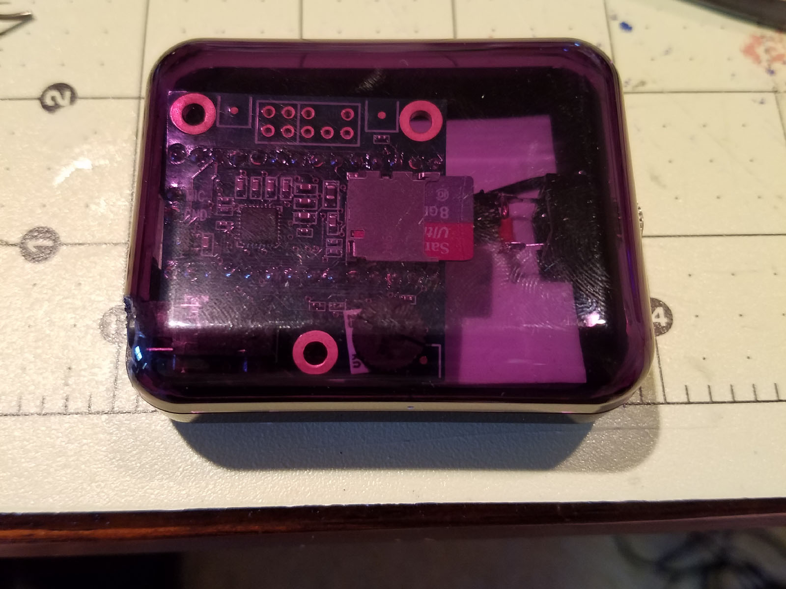
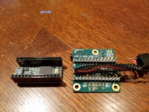
Teensy and Audio Shield with headers and sockets soldered and connected together
See how easy this is so far? By now, you should have
- Arduino and TeensyDuino installed
- Sockets and header pins soldered onto Teensy and Audio Shield and boards connected
- Sound files loaded on micro USB card and card installed in SD card reader of Audio Shield
Loading the Software
Connect the Teensy with the USB to micro USB cable. Plug the micro USB end to the Teensy and the USB end to your computer. You should see the on-board LED light up. This means you have power 🙂 Next:
- In the Arduino software, go to Tools > Board and make sure to select the correct board (in this case, Teensy 3.2/3.1).
- Go to Tools > Port and select the correct serial port (the one your Teensy is connected to)
- Download the tktalkie.ino file from the Github repo (remember where you download it!)
- Go to File > Open in the Arduino software and open up the tktalkie.ino file
Once the file is opened, click the “Upload” button (the one that looks like an arrow pointing right.) If everything is connected correctly, the sketch should compile and load onto your Teensy. Then the board should restart and you should hear the STARTUP.WAV file play (oh yeah don’t forget to either connect your speaker to the headphone jack on the audio shield or plug in some headphones…)
If the sketch doesn’t load (i.e. you get an error in the Arduino window), make sure your pins are connected correctly and that you have selected the correct board and serial port (see above.) Also make sure the volume is turned up on your speaker 🙂
Then unplug everything because you have some more soldering to do…
About the Software
I used the BitCrusher component to compress the voice and lower the pitch just a tad so it sounds like a crappy old walkie talkie. The software sketch is commented pretty heavily so that you know what’s going on. Feel free to play around with it and tweak to your liking! Again, take a look at the READ.me file on the Github repo.
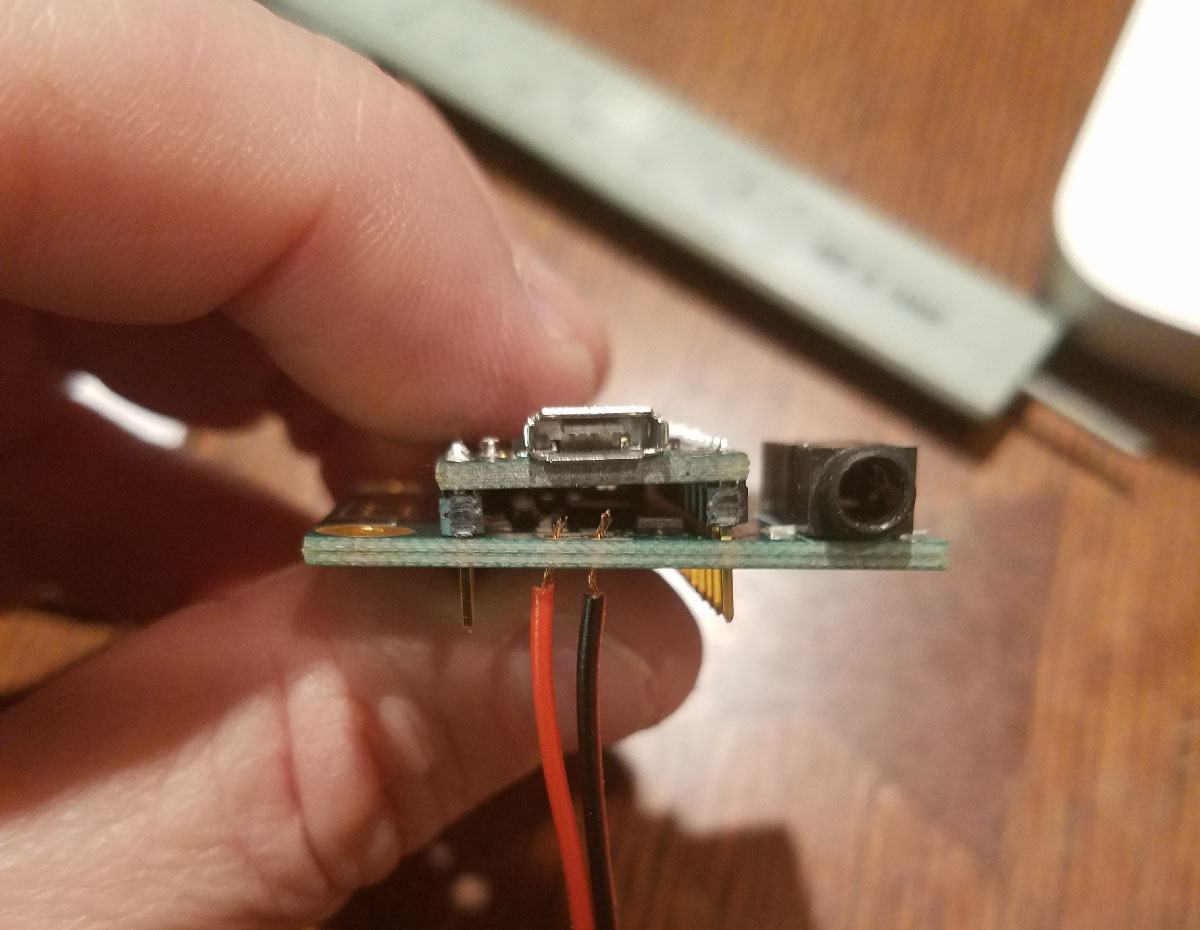
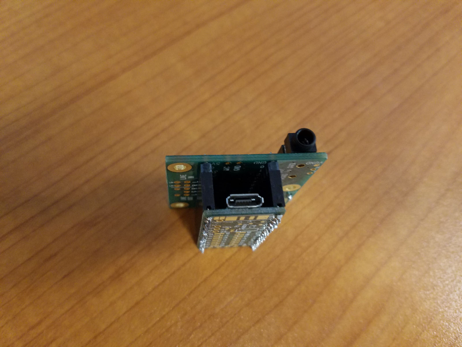
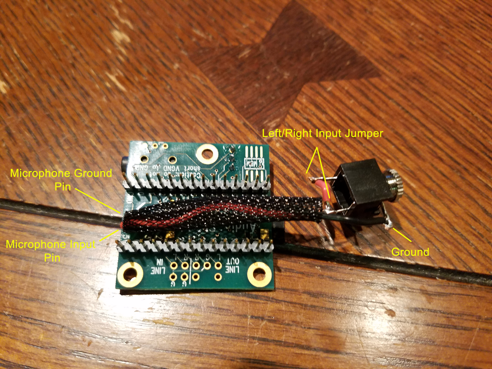
Connecting the Microphone

Panel mount 1/8″ stereo input jack soldered to Audio Shield. Note the jumper between the left and right input channels on the jack since the microphone input on the Audio Shield is mono.
You can either use the microphone input on the audio shield or the line-in. It’s easier to use the microphone (IMO), but feel free to use the line-in if you want (that just means you’ll need to use some type of powered input signal.) The microphone is mono with a single positive lead and a ground, and I used a stereo input jack, so I just jumped a wire between the left and right pins on the jack and then soldered the microphone to the board. Make sure you solder the ground on the input jack to the ground on the audio shield.
Once this is done, you have a “complete” system. You should be able to connect everything back up, including connecting a microphone, fire up the board (you can use the 5V power supply at this point or just keep using your computer’s USB port,) hear the STARTUP.WAV file, then start talking and hearing voice effects!
Now It Needs a Box…
The last part of this project is putting it in a protective box so that you can troop with it without worrying about it getting damaged. I went to the local Fry’s and looked for a project enclosure and actually bought a few to try out, but they were all to big or not tall enough or too tall (and as you know, you have limited room in the TK outfit…)
As luck would have it, I had recently upgraded my phone to a Galaxy S7 and as it turns out the plastic box that the headphones come it is almost perfect for the job! The boards can squeeze in there and be held pretty safely in place! Yay!
So in the last part of this tutorial I’ll show you how I mounted it in the headphones case 🙂
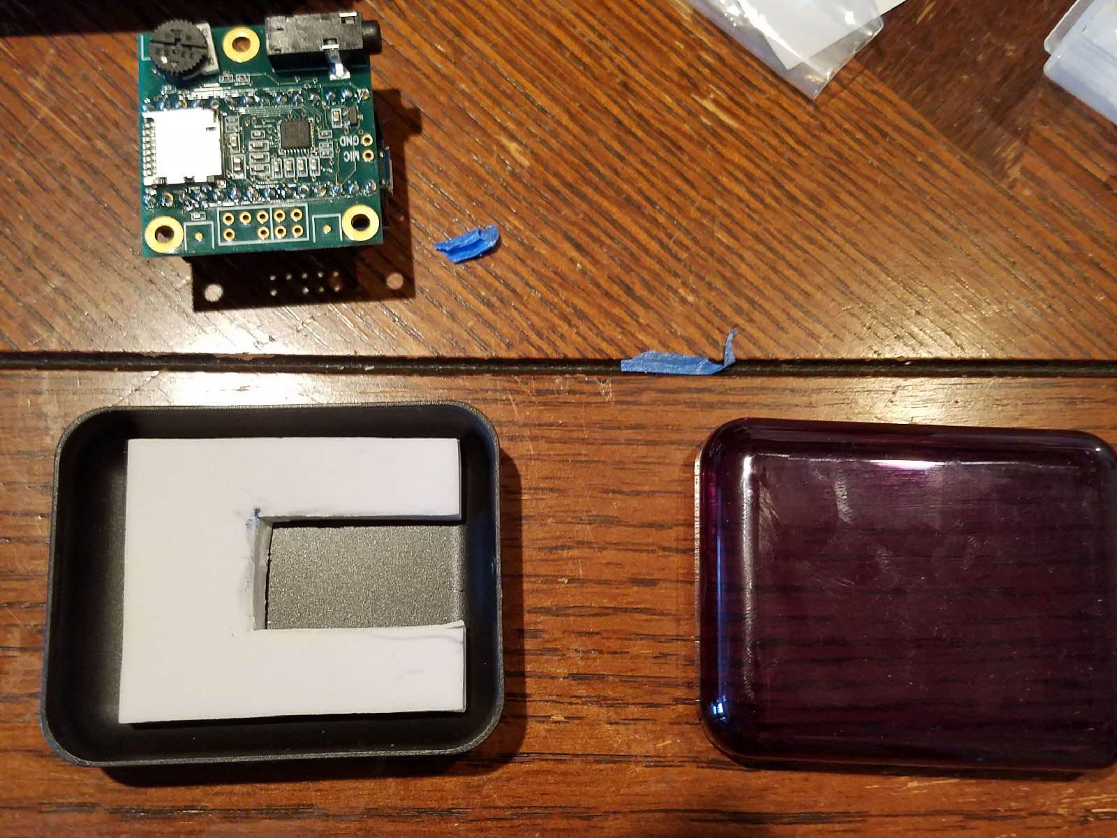
Make a Base
In order to prevent the board from rattling around inside the box once it was closed, I took the sticky foam pads from inside the TK helmet (if you’ve done any helmet upgrades you know what I’m talking about 😉 ) and cut out a rectangle shape and stuck it to the bottom of the case.

Trimmed down sticky pad from inside the TK helmet.
The only bad thing about the case is that it curved on the sides, so in order to get the board to sit flush I would have to make openings a little larger in order to get to the connections. Not a big deal, I need this to work, not look pretty (although…to be honest…I would like it to look SOMEWHAT pretty) since it will be mounted behind my chest plate.
Next, I test fitted the boards and marked where I would have to make openings for the micro USB, headphone and microphone jack connections. Since this case has a top and a bottom, I would have to make cuts in both.
Make Some Holes
After test fitting and marking where to cut, I got out the trusty Dremel with a cutting wheel and some needle files (if you don’t have needle files….bro? Do you even cosplay?) Also an X-acto knife comes in handy for some finer trimming.
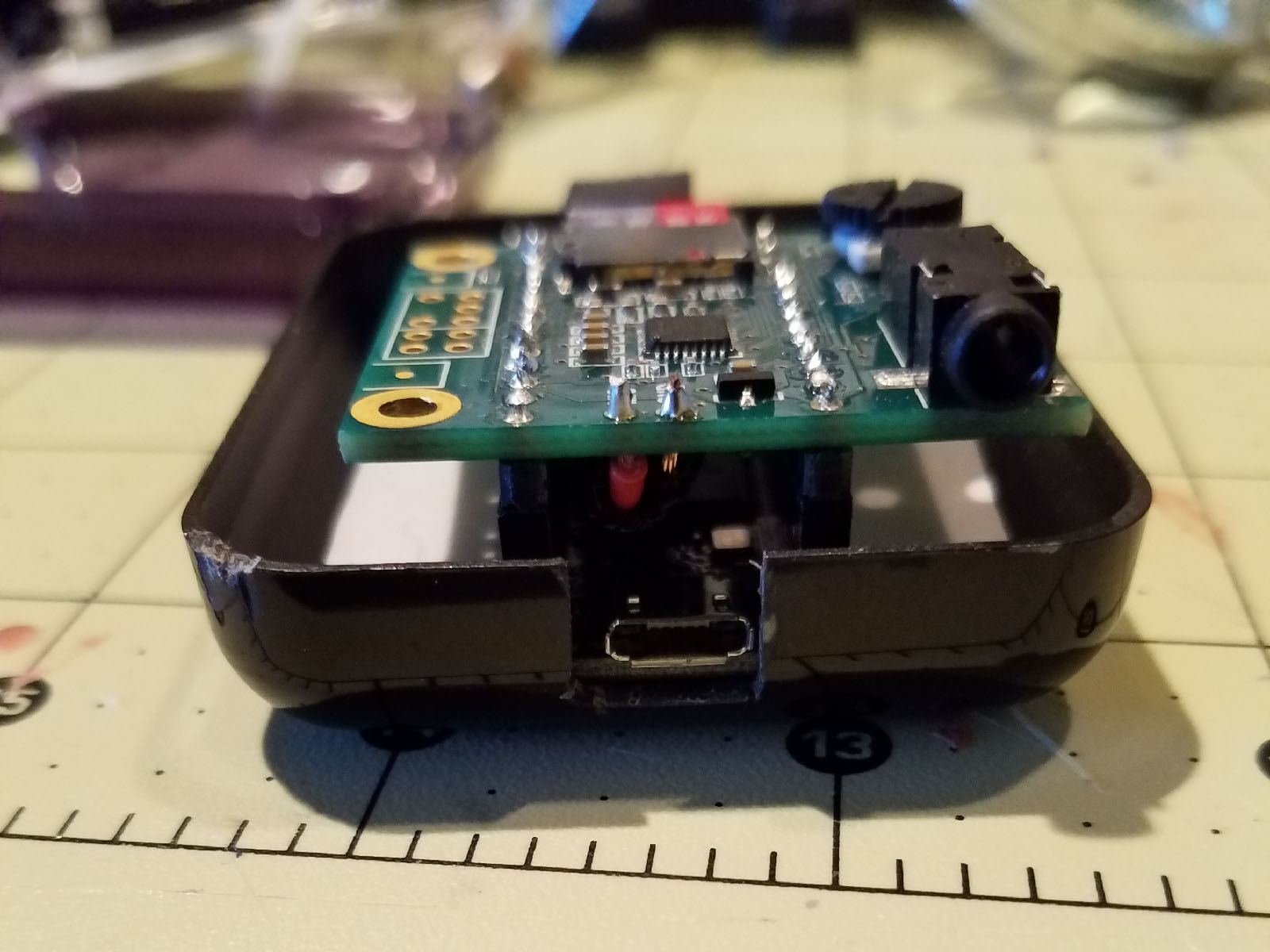
I cut the opening for the micro USB first since it was on the bottom and I needed to make sure it went low enough so that when the boards are resting on the bottom of the case I could plug in the micro USB cable.

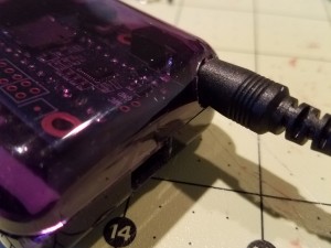
Cutting the opening for the micro USB connection.
Next, I marked where the headphone jack would need to be accessible through the top part of the case and started by drilling a 1/16″ pilot hole, then eventually ended up using a 1/4″ drill bit and widening the opening to make sure the speaker connector could be plugged in. Each time I cut an opening, I used the needle files to smooth it out and the x-acto knife for fine trimming as the plastic was soft enough that it started to melt from the Dremel or drill if I went too fast.
At first the opening was too small, so I had to go back with a larger bit to open it up more and then use the files to smooth it out so the entire connector would fit.
Also, once I had the openings for the micro USB and headphones cut out, I put the boards in the box and closed it up for another test fit and noticed that I didn’t actually have the clearance I though I had so the board kind of sat lop-sided. Oops! Oh well, like I said, this needs to work more than it needs to look pretty, plus it ended up holding the board pretty securely in place!

Oops! Turns out the box was not as tall as I thought! I could still access the connections, though…so all good.
Microphone Jack
I chose a panel mount microphone jack because I knew that whatever I ended up using for an enclosure, I would want it accessible from the outside (as is normal.) However, with this one, I would need to make cuts in both the bottom and top of the case in order to get it to fit.

Had to make an opening in the bottom of the case and then cut a notch out of the lid for the microphone jack.
Putting It All Together
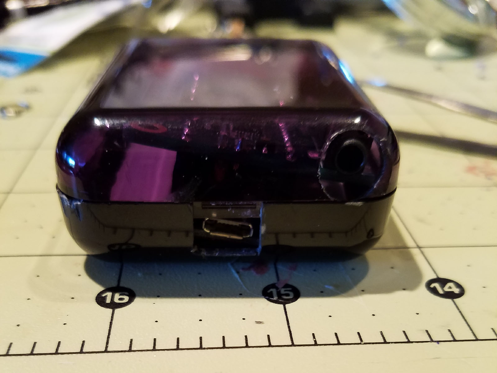
Once I was done with the openings for the connections, I was able to close up the case, hook everything up and voila! It works great!

Case closed.
I hope this tutorial was helpful, and I hope if you make this project you have as much fun as I did. Like I said, there are LOTS of things you can do to this project (like add a PTT button if you want.)
For the Empire!
 t really….almost, though…
 It also was a great way to road test the